Jeep Parts Wiki | Ford Parts Wiki
Home | Search | Browse
|
Body Service Manual August 1964 |
|
Prev

 Next
Next
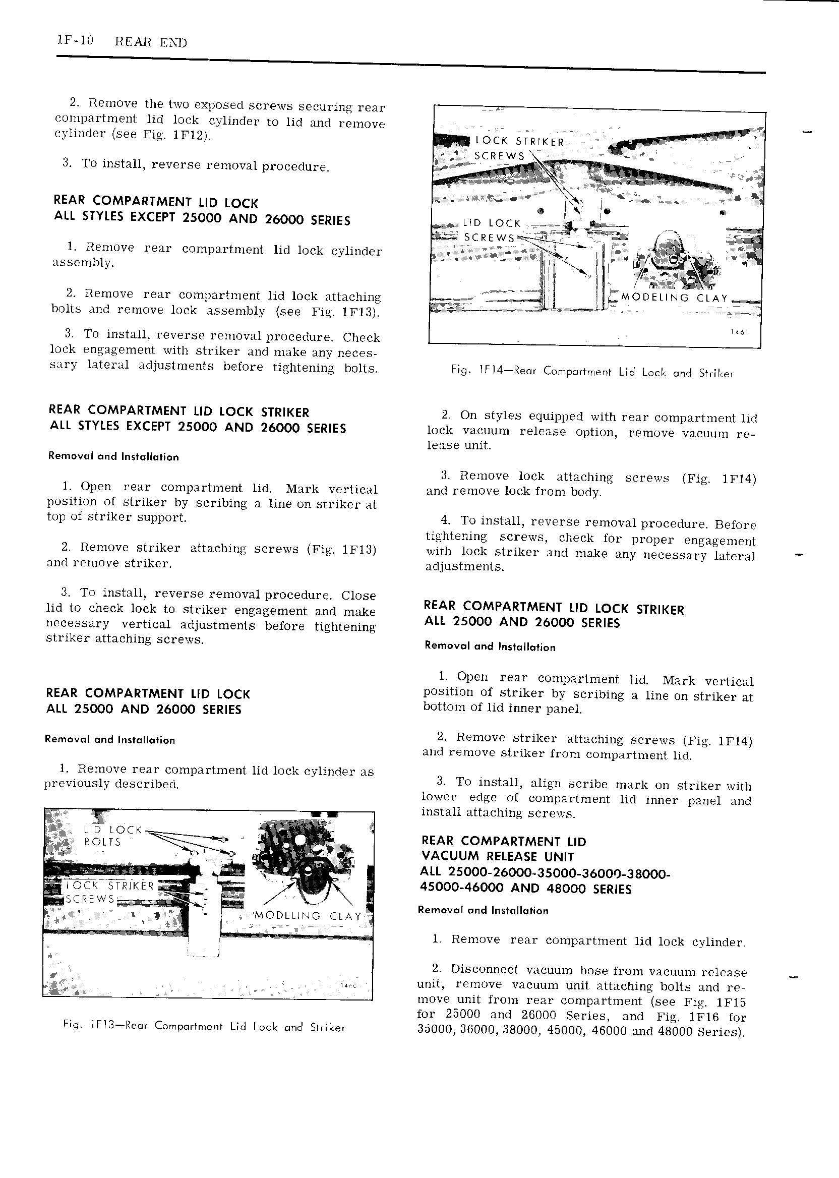
lF l0 REAR END 2 Remove the two exposed screws securing rear compartment lid lock cylinder to lid and remove cylinder see Fig lFl2 LOCK SWIKER SCREWS 3 To install reverse removal procedure l 4 ai M i I L L t I I REAR COMPARTMENT LID LOCK M e I ALL STYLES EXCEPT 25000 AND 26000 SERIES LID LOCK 51 taxis ssJ 2 V Us NWS sc e I J t rt l Remove ieai compartment lid lock cylinder ax 5 ia assembly iii T l we i s 2 Remove rear compartment lid lock attaching ciirir k MODEUNG CLAY bolts and remove lock assembly see Fig lFl3 M V 3 To install reverse removal procedure Check lock engagement with striker and make any neces sary lateral adjustments before tightening bolts Fig IFI4 Re Comportment Ltd Lost and Sh iLet REAR COMPARTMENT LID LOCK STRIKER 2 On styles equipped with rear compartment lid ALL STYLES EXCEPT 25000 AND 26000 SERIES lock vacuum release option remove vacuum re lease unit Removul und ns lI i n 3 Remove lock attaching screws Fig lFl4 l Open rear compartment lid Mark vertical and remove lock from body position of striker by scribing a line on striker at top oi striker support 4 To install reverse removal procedure Before tightening screws check for proper engagement 2 Remove striker attaching screws Fig lFl3 with lock striker and make any necessary lateral and remove striker adjustments 3 To install reverse removal procedure Close r M REAR COMPARTMENT LID LOCK STRIKER lid to check lock to stiikei engagement and make ALL 25000 AND 26000 SERIES necessary vertical adjustments before tightening striker attaching screws Rem v I und InsI I Ii n l Open rear compartment lid Mark vertical REAR COMPARTMENT LID LOCK position of striker by scribing a line on striker at ALL 25000 AND 26000 SERIES bottom of lid inner panel m rd itTii liei JigigiiiiSE KSagig lm t z L l ll k l d 1 F j f E Limlplrnnem K DC oy m El lg 3 To install align scribe mark on striker with previously described lower edge of compartment lid inner panel and install attaching screws i e LID LOU I REAR COMPARTMENT LID Mi tT V t L 4 gm J ggg VACUUM RELEASE UNIT ga a og V ALL 25000 26000 35000 36000 38000 OC g R KER L 45000 46000 AND 48000 SERIES CEE N5 awv l Removal r1d IDSTDHCHIOVI MODELING CLAY 4 l Remove rear compartment lid lock cylinder I 2 Disconnect vacuum hose from vacuum release tn unit remove vacuum unit attaching bolts and re move unit from rear compartment see Fig 1Fl5 for 25000 and 26000 Series and Fig lFl6 for Fig lFI3 Re Compartment Lid Lock ond Sniker 35000 36000 38000 45000 46000 and 48000 Series

 Next
Next