Jeep Parts Wiki | Ford Parts Wiki
Home | Search | Browse
|
Body Service Manual August 1964 |
|
Prev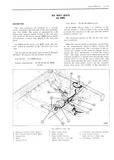
 Next
Next
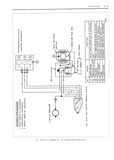
IL 34 MLECTRICAIJ they seat motor A When the control switch lever is 2 If tester does not light there is an open or released the switch contacts open a spring returns short circuit between switch and power source the shaft dog and solenoid plunger to their original position disengaeing them from the gear dog D Checking the Seat Control Switch CIRCUIT CHECKING PROCEDURES NOTE In the following operations which specify the seat control switch to be actuated a switch It may be necessary to use only one or all of the that has been checked for proper operation may pr cedt1rt s outlined to locate an electrical failure be connected to the switch block If a switch is in the circuit Lf the location ofthe failure is evi not available a three way jumper wire can be dent follow only the steps required to check the made to perform the switch function The jumper affected wire or coniponcnt It the location of the wire and the switch locations to be connected to failure is not evident follow the procedure as out obtain a specific movement of the seat are shown lined Before performing any extensive check pro in Figures lL49 35 35 38000 with switch in cedures check the seat adjuster drive cables lor seat side panel II 50 38000 with switch in arm proper attachment In addition study the seat cir rest lL5l 68000 series If a jumper wire is cult diagrams to become familiar with the seat used letter the locations on the switch block as circuit bw l it ur s II 44 for I5 IG 2 5 26 45 46 indicated in the illustration Details outlining 40000 series lL45 46 for 35 36 38000 lL47 for the making and use of the jumper wire follow 68000 series the checking procedurs A Check Few Circuit Cjmtmuity at Ciwuit 1 Obtain switch or jumper wire and connect to Brpakgr switch block t e t tet t one est nett tm to battery site of 0i i Swii 1 Si i S i 1 c wiihiiew circuit breaker and ground other lead If tegtpp Switcli U1 1l1mI P1 Wire but did not operate with AMES not hghp there is an UPEI O1 Short Ciwuit in original switch the original switch is detective feed circuit to breaker 3 Check all movements of seat adjuster 2 To check circuit breaker disconnect the out put feed wire the wire opposite the power source feed to the breaker from the breaker and with test E Cheek Feed Cjypuit Cgmhmity At Remy light check terminal from which the wire was dis on Seat Motor connected lf tester does not light circuit breaker IF 1K1 J 7Pl tiV l Disengage 3 wire connector body from the seat motor relay terminal 3 45 46 48000 68000 Series Check feed cir iiftlit Cfititiiiliity HT fuse I l l k 2 Insert one test light lead into the relay power feed connector slot on the harness and ground the other test light lead H checking Relay Assembly at Shroud 35 3G 38OOO SCUQS 3 If tester does not light there is no current at 1 v I H 1 1 k 1 end of feed wire Failure is caused by an open or Wit 1 test ig it c in k icay feed 01 ange black Short in COG Circuit stripe It tester does not light there is an open or short circuit between relay and circuit breaker 2 rant tgntttttt Switch tm and with test nant F Checkiiis Wires Between C ti 1 Switch mid cln cl output terminal of relay red white stripe I I O1 R 1 iY Il tester does not light the relay is inoperative I or there is a short or open circuit between ignition D1S lltEH C i 3 W1l harness connector from re switch pink and relay assembly Check fuse at MY Rt m t Y dash panel 2 Insert one test light lead into the motor field connector slot on harness and ground the other C Check Feed Circuit Continuity at Seat 1 ld Contrt l Switch 3 Actuate seat switch to energize field wire V 1 Connect one test light lead to feed terminal of being tested switch block and ground other test lead to body metal 4 If tester does not light there is no current at