Jeep Parts Wiki | Ford Parts Wiki
Home | Search | Browse
|
Body Service Manual August 1964 |
|
Prev
 Next
Next
231115
231115
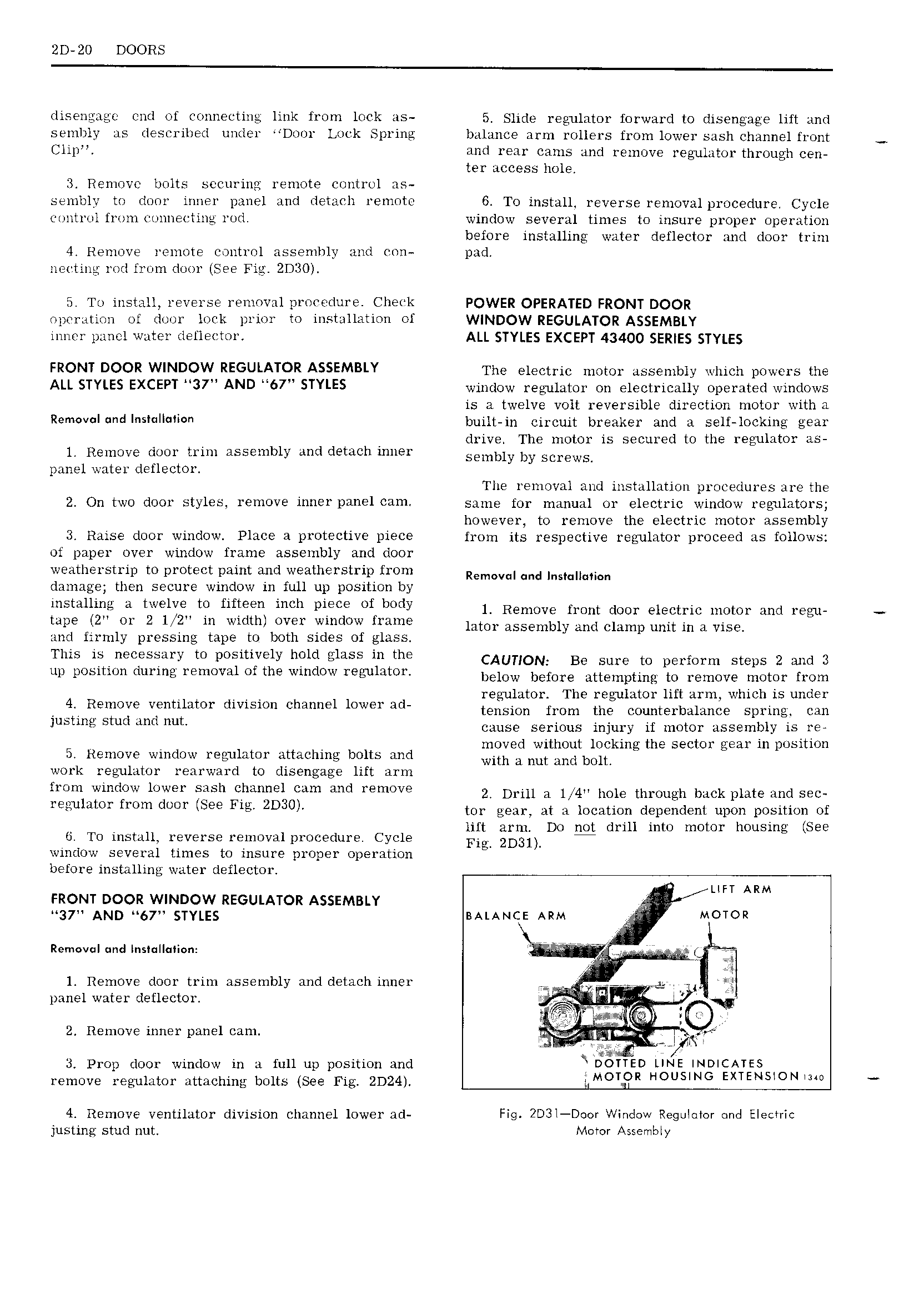
2D 20 DOORS disengage end of coniiectiiig link from lock as 5 Slide regulator forward to disengage lift and sembly as described under Door Lock Spring balance arm rollers from lower sash channel front Clip mid rear 231115 and remove regulator through cen ter access hole Remove bolts securing remote control as sembly to door inner panel and detach remote 6 T0 install reverse removal procedure Cycle control from lJllIlE1 Tlllg rod window several times to insure proper operation before installing water deflector and door trim 4 Remove remote control assembly and con pad ne tinL rod from door See Fig 2D30 5 To install reverse removal procedure Check POWER OPERATED FRONT DOOR t p p tti m or door lock prior to installation of WINDOW REGULATOR ASSEMBLY inner panel water deflector ALL STYLES EXCEPT 43400 SERIES STYLES FRONT DOOR WINDOW REGULATOR ASSEMBLY The electric motor assembly which powers the ALL STYLES EXCEPT M37 AND H67 STYLES window regulator on electrically operated windows is a twelve volt reversible direction motor with a R I dI II T built in circuit breaker and a self locking gear drive The motor is secured to the regulator as 1 Remove door trim assembly and detach inner Sammy by Screws panel water deflector The removal and installation procedures are the 2 OH two d001 StYl S 1 m0V i 91 DH T 3m Same for manual or electric window regulators however to remove the electric motor assembly 3 Raise door window Place a protective piece from its respective regulator proceed as follows of paper over window frame assembly and door weatherstrip to protect paint and weatherstrip from Removal and Insmumion damage then secure window in full up position by 1 St 1 time T0 fiftm mh pim 0f DMV 1 Remove front door electric mm an regu tape 2 or 2 1 2 in width over window frame htm assembly and Clamp unit in A visa and firmly pressing tape to both sides of glass This is necessary to positively hold glass in the CAUTION BG Sum to perform Steps 2 and 3 up position during removal of the window regulator below before attempting to remove mmm from 4 Remove vemihtor division Channel lower lad regulator The regulator lift arm whichlis under tension from the counterbalance spring can JUSTIHQ stud fl Ut gauge serious injury if motor assembly is 1 V V V moved without locking the sector gear in position 1 Remove window regulator attaching bolts and with 3 nut and bolt work regulator rearward to disengage lift arm from window lower sash channel CLUTI and remove 2 Drill A 1 4ii hole through buck plate and S9C EEEUTHTOE fm TORT SEQ Fig 2D30 tor gear at a location dependent upon position of V lift arm Do not drill into motor housing See 0 To install reverse removalprocedure Cycle Fi 2D31 window several times to insure proper operation before installing water deflector P LIFT ARM FRONT DOOR WINDOW REGULATOR ASSEMBLY fz 37 AND 67 STYLES BALANOE ARM A MOTOR Rem v I mid InsI II Ii n 4 V 1 Remove door trim assembly and detach inner r V gg wp I panel yatei deflectoi 2 Remove inner panel cam QI 1 a s L x 3 Prop door window in a full up position and DOTTED LINE INDICATES remove regulator attaching bolts See Fig 2D24 1 OTOR HOUSING EXTENSION 4 Remove ventilator division channel lower ad Fig 2D3l D r Window Regolulor ond Electric justin stud nut Mover Assembly