Jeep Parts Wiki | Ford Parts Wiki
Home | Search | Browse
Prev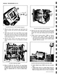
 Next
Next
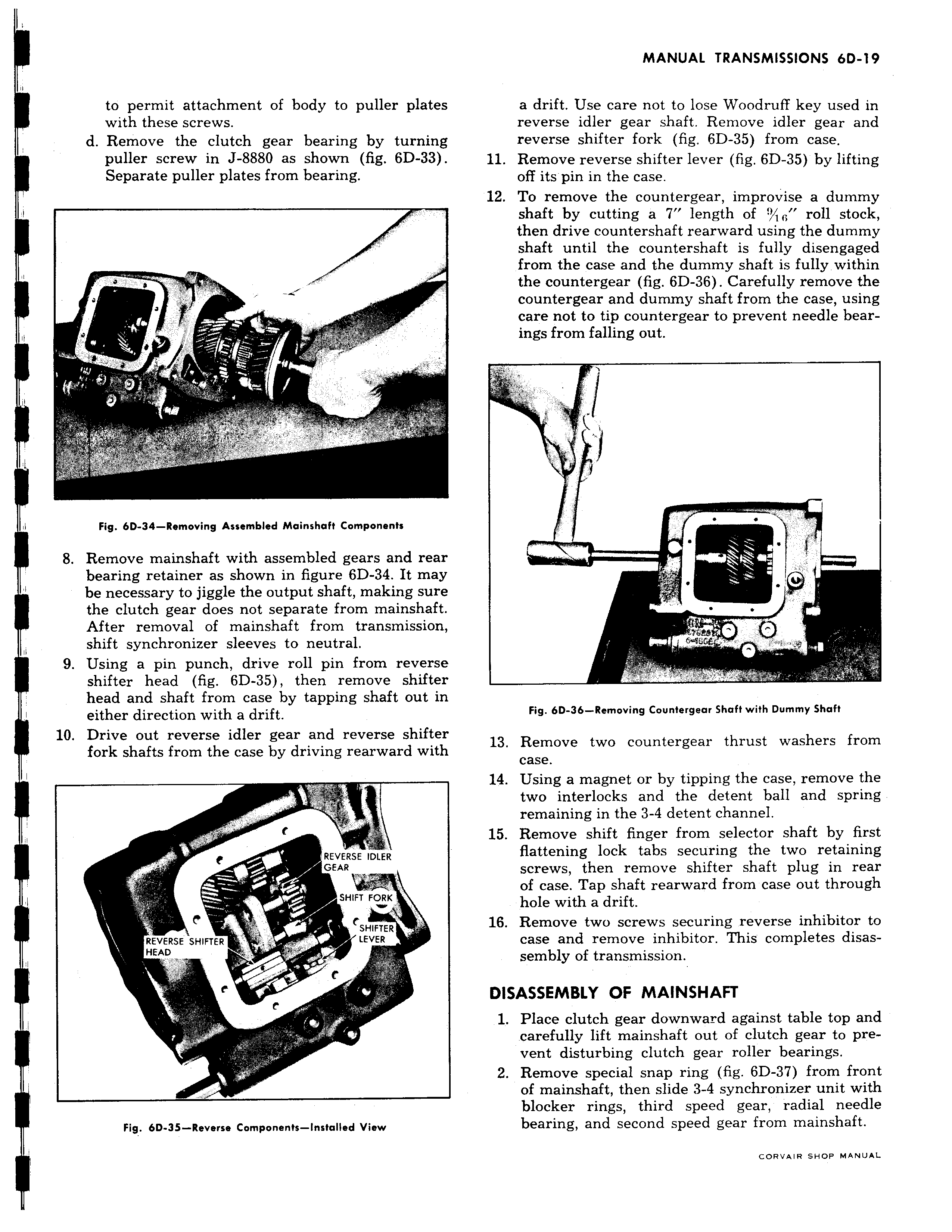
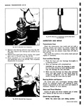
to permit attachment of body to puller plates with these screws d Remove the clutch gear bearing by turning puller screw in J 8880 as shown fig 6D 33 Separate puller plates from bearing r I P f Fig 6D 34 Removing Assembled Mainshaft Components 8 Remove mainshaft with assembled gears and rear bearing retainer as shown in figure 6D 34 It may I be necessary to jiggle the output shaft making sure the clutch gear does not separate from mainshaft After removal of mainshaft from transmission i shift synchronizer sleeves to neutral 9 Using a pin punch drive roll pin from reverse shifter head fig 6D 35 then remove shifter head and shaft from case by tapping shaft out in either direction with a drift 10 Drive out reverse idler gear and reverse shifter fork shafts from the case by driving rearward with v REVERSE IDLER E GEAR SHIFT FORK C SHIFTER REVERSE SHIFTER LEVER HEAD r F Fig bD 35 Reverse Components Installed View a drift Use care not to lose Woadruff key used in reverse idler gear shaft Remove idler gear and reverse shifter fork fig 6D 35 from case 11 Remove reverse shifter lever fig 6D 35 by lifting off its pin in the case 12 To remove the countergear improvise a dummy shaft by cutting a 7 length of yl roll stock then drive countershaft rearward using the dummy shaft until the countershaft is fully disengaged from the case and the dummy shaft is fully within the countergear fig 6D 36 Carefully remove the countergear and dummy shaft from the case using care not to tip countergear to prevent needle bearings from falling out 1 Fig 6D 36 Removing Counfergear Shaft with Dummy Shaft 13 Remove two countergear thrust washers from case 14 Using a magnet or by tipping the case remove the two interlocks and the detent ball and spring remaining in the 3 4 detent channel 15 Remove shift finger from selector shaft by first flattening lock tabs securing the two retaining screws then remove shifter shaft plug in rear of case Tap shaft rearward from case out through hole with a drift 16 Remove two screws securing reverse inhibitor to case and remove inhibitor This completes disassembly of transmission DISASSEMBLY OF MAINSHAFT 1 Place clutch gear downward against table top and carefully lift mainshaft out of clutch gear to prevent disturbing clutch gear roller bearings 2 Remove special snap ring fig 6D 37 from front of mainshaft then slide 3 4 synchronizer unit with blocker rings third speed gear radial needle bearing and second speed gear from mainshaft CORVAIR SHOP MANUAL