Jeep Parts Wiki | Ford Parts Wiki
Home | Search | Browse
|
Body Service Manual August 1964 |
|
Prev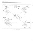

 Next
Next
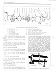
FOLDING TOP 21 31 HYDRO LECTRIC SYSTEM The high pressure hydro lectric unit used in the being forced under pressure from disconnected convertible bodies consists of a 12 volt reversible lines and causing damage to trim or body finish type motor a rotor type pump two hydraulic lift cylinders and an upper and lower hydraulic hose 11 Disconnect hydraulic lines and cap open fittings assembly The unit is installed in the body di to prevent leakage of fluid Fig 2158 Use a rcctly behind rear seat back Fig 2158 cloth to absorb any leaking fluid then remove unit from rear compartment Figure 2159 illustrates and identifies the indi yidual parts of the motor and pump assembly ns H i n NOTE when ee Vi i e the mljmr assembly Or 1 lf a replacement unit is being installed fill pump end plate assembly it 1S XU m 1Y Wl ygggm gjy unit with specified Delco No 11 Hydralu l that the 11 Shaft O rm nc Fluid GM Hydrauiie Brake rnnn supei 1m 11 seal is properly installed over the motor arma O1 its equivalent See Fiuhm Of Hvd1 0 LE U i ture shaft and into the pump end plate assembly R S w n prior to installing the pump rotors or the motor Shim dove mu 2 Connect hydraulic hoses engage attaching grommets in panel and connect wiring MOTOR AND PUMP ASSEMBLY 3 Connect battery and operate top through its Removal up and down cycles until all air has been bled from hydraulic circuit See Filling of Hydro V Lectric Reservoir 1 Operate folding top to full up position 2 Discmmgct pnqitive battgw mblg 4 Qheck connections for leaks and recheck fluid level in reservoir Bfphce protective Covering Over rear Seat 5 lnstall all previously removed parts cushion and back 4 Working inside body detach front edge of fold RESERVOIR TUBE ing top compartment bag from rear seat back panel Disassembly from Motor und Pump Assembly 5 Working on inside of body over rear seat back Femgve pump and motor Shield gttuphjug 1 Remove motor and pump assembly from body screws and remove shield 2 Scribe a line across pump end plate and 6 Remove clips securing wire harness and reservoir tube to insure a correct assembly of hydraulic hose to rear seat back panel Fig parts See Fig 2160 2158 T Disconnect motor leads from wire harness and HVDRAULIC UNE CONNECWNS ground attaching screws Fig 2158 1 wmnno rmzuess corwecron 8 To facilitate removal apply a rubber lubri HVDRAUUC HOSE j r g cant to pump attaching grommets then carefully RETAINING CUPS 4 iQi s T Qi I Ejijf disengage grommets from floor pan Fig 2158 2 keg 7 7 e 9 Place absorbent rags below hose connections Z Ziifll ii i oe Et i r Moron me rum and end of reservoir gg jjn xa GROMMET lx si 3 1 10 With a straight bladed screwdriver vent reservoir by removing filler plug then reinstall Q ef M g plug NOTE Venting reservoir is necessary in this sealed in unit to equalize air pressure in r Z J reservoir to that of the atmosphere This oper ation pi evt n s the ptissiminy of iiyemuiic num 2 58 M 1d PMP A S m lv