Jeep Parts Wiki | Ford Parts Wiki
Home | Search | Browse
|
Body Service Manual August 1964 |
|
Prev

 Next
Next
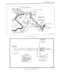
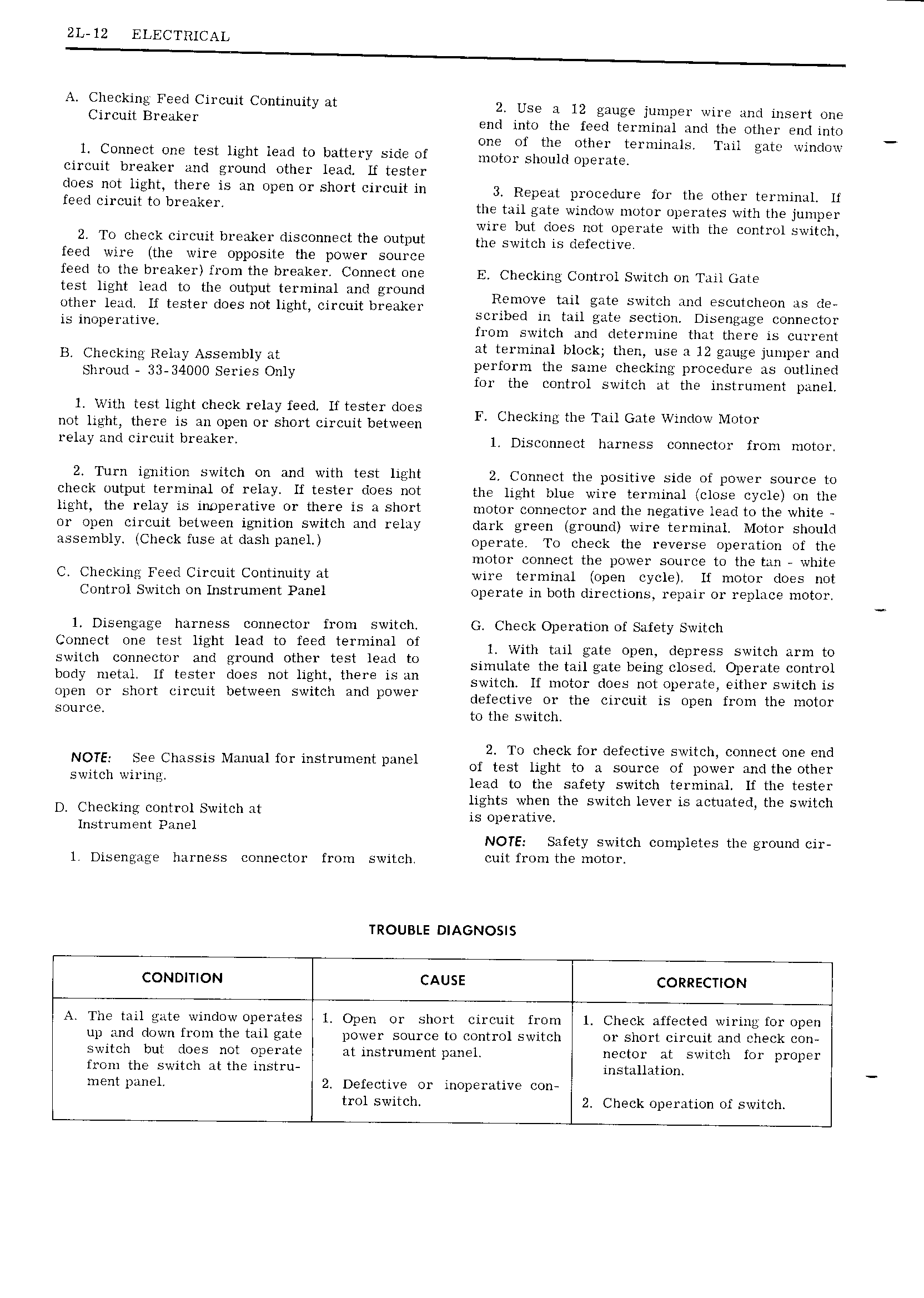
2L 12 ELECTRICAL A gl1E i F i i Circuit Continuity at 2 Use a 12 gauge jumper wire and insert one lnrul 19 tr end into the feed terminal and the other end into one of the other terminals Tail gat if I 1 Connect one test light lead to battery side of m tm Slmum Op mtea L m U circuit breaker and ground other lead Lf tester thves hvt heht there is an Open Or Sh01 t i itih 3 Repeat pmcetiure for the other terminai ix feed Cucmt to bYE nk I the tail gate window motor operates with the jumper Z I k N h wire but does not operate with the control switch To ciec circui Jreaker disconnectt e output the Switch is dm E Ctw feed wire the wire opposite the power source feed to the breaker from the breaker Connect one E Checking Control Switch on Tail jate test light lead to the output terminal and ground Remove ml mt S t 1 I I I I other lead lf tester does not light circuit breaker I f M lm 8bLu Cum ib scribed in tail gate section Disengage connector is inopeiative V V trom switch and cletcrmine that there is current B4 Chsckmg Remy Assembly at at terminal block then a 12 gauge jumper and perform the same checking procedure as outlined Shroud 5 3 34000 Series Only tor the control switch at the instrument panel 1 l k l 1 f o 2 1th test ight dmc re Ay mel 1 Ritter web F Checking the Tail Gate Window Motor not light there is an open or short circuit between relay and circuit breaker 1 Disconnect harness connector from motor 2 Turn ignition switch on and with test light 2 Connect the positive side of power source to check output terminal of relay lf tester does not the light blue wire terminal close cycle on the light the relay is inoperative or there is a short motor connector and the negative lead to the white or open circuit between ignition switch and relay dark green ground wire terminal Motor should assembly Check fuse at dash panel operate To check the reverse operation of the motor connect the power source to the tan white C Checking Feed Circuit Continuity at wire terminal open cycle lf motor does not Control Switch on Instrument Panel operate in both directions repair or replace motor 1 Disengage harness connector from switch G Check Operation of Safety Switch Connect one test light lead to feed terminal of 1 with mu mtg Open depress Switch Mm to Swlch C m BCt and ground Othvgr mst lead to simulate the tail gate being closed Operate control body mettti ii tester does not heht there 15 11 switch If uigtgr does not operate either switch is open or short circuit between switch and power defective Ol the Circuit is Open fmm the mmm SOu E to the switch V 2 To check for defective switch connect one end NOTE See Chassis Manual for instrument panel Of test light to a source Of power andthe other Swltch wu mg lead to the safety switch terminal If the tester U kv T 1 S t I t lights when the switch lever is actuated the switch D tec 1l1g con ro Dwi ci a S 0 mti E Instrument Panel 1 1 NOTE Safety switch completes the ground cir 1 Disengage harness connector from switch Cui f1 0 1th m0t01 TROUBLE DIAGNOSIS CONDITION CAUSE CORRECTION A The tail gate window operates 1 Open or short circuit from 1 Check affected wiring for open up and down from the tail gate power source to control switch or short circuit and check con switch but does not operate at instrument panel nector at switch for proper from the switch at the instru installation ment panel 2 Defective or inoperative con trol switch 2 Check operation of switch

 Next
Next