Jeep Parts Wiki | Ford Parts Wiki
Home | Search | Browse
|
Body Service Manual August 1964 |
|
Prev
 Next
Next
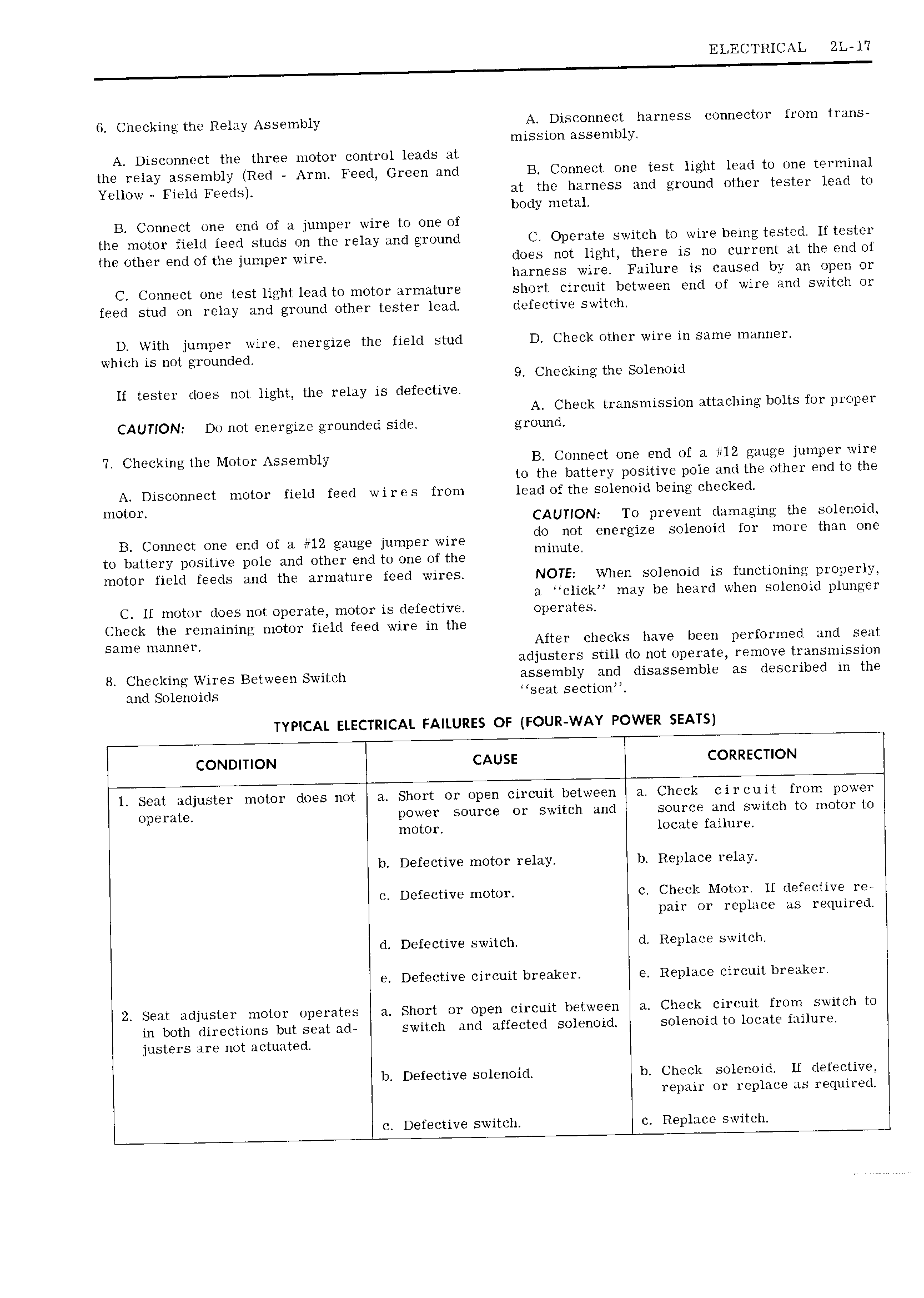
ELECTRICAL 2L l I 6 Checking the Relay Assembly A Disconnect harness connector from trans mission assembly Disconnect the three motor control leads at the relay assembly Red Arm Feed Green and E Connect one test light lead to one terminal Yellow Field Feeds at the harness and ground other tester lead to body metal B Connect one end of a jumper wire to one of the motor field feed studs on the relay and ground C Operate switch to wire being tested If tester the other end of the jumper wire does not light there is no current at the end of harness wire Failure is caused by an open or C Connect one test light lead to motor armature short circuit between end of wire and switch or feed stud on relay and ground other tester lead defective switch D With jumper wire energize the field stud D Check other wire in same manner which is not grounded 9 Checking the Solenoid if tester does not light the relay is defective A Check transmission attaching bolts for proper CAUTION Do not energize grounded side ground 7 Checking the Motor Assembly B Connect one end of a 12 gauge jumper wire to the battery positive pole and the other end to the A Disconnect motor field feed wires from lead of the solenoid being checked to mo U1 CAUTION To prevent damaging the solenoid B Connect one end of a H2 jumper wire iiihfft energlzg Solenoid fm more umn me to battery positive pole and other end to one of the I motor field feeds and the arinature feed wires NOTE When solenoid is functioning properly a click may be heard when solenoid plunger C lf motor does not operate motor is defective operates Check the remaining motor field feed wire in the same manner After checks have been performed and seat adjusters still do not operate remove transmission 8 Checking Wires Between Switch assembly and disassemble as described in the and Solenoids seat section TYPICAL ELECTRICAL FAILURES OF FOUR WAY POWER SEATS CONDITION CAUSE CORRECTION l Seat adjuster motor does not a Short or open circuit between a Check circuit from power operate power source or switch and source and switch to motor to motor locate failure b Defective motor relay b Replace relay c Defective motor c Check Motor lf defective ree pair or replace as required d Defective switch d Replace switch e Defective circuit breaker e Replace circuit breaker 2 Seat adjuster motor operates Short or open circuit between a Check circuit from switch to in both directions but seat ad switch and affected solenoid solenoid to locate failure justers are not actuated b Defective solenoid b Check solenoid lf defective repair or replace as required c Defective switch c Replace switch