| Book |
Page |
Context |
 |
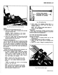 |
short cylinaer studs to a projected length of 7 9 16 fig 110 using Tool J 8354 1 3 8 24 fig 109 For easy measuring of stud installed length measure from Tool ...
Studs 2 Install engine rear mounting bracket studs to a projected length of 4 9 16 fig 110 using Tool J 8354 3 3 811 16 NOTE Rear mounting bracket studs should be torqued ...
Inspect for cracks at flange for mounting Delcotron w 1 F I 1 4 3 Fig 110 Stud Installed Length |
 |
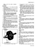 |
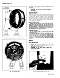
brush holder springs may be reused TESTING ROTOR The rotor may be checked electrically with a 110 volt test lamp or an ohmmeter Grounds Connect test lamp or ohmmeter from either slip ring ...
indicates shorted windings Refer to Specifications at the end of this section TESTING STATOR Grounds Connect a 110 volt test lamp or an ohmmeter from any stator lead to the stator frame If test lamp |
 |
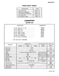 |
Mount Nuts Rear Mount to Frame CARB SEC APPLICATION 95 H P Engine Syn or P G 110 H P Engine Syn 110 H P Engine P G 140 H P Engine Primary |
 |
 |
United States and Canada The Corsa model and all Corvair models equipped with the Turbo Air 110 H P engine are designed to operate most efficiently on Premium gasoline Regular gasoline may vary in octane |
 |
 |
Special Wire Part of Harness 1 8 ohms AC 44FF AC 46FF 110 140 and 180 hp 95 hp 14 mm 14 mm 030 035 15 20 lb ft 0698 GORVw SHOP WelJlleI |
 |
 |
Rear Primary 9 01 Secondary 9 75 IE 16 IANICAL Hi Perf 4 x 1 Turbo Charged 110 4400 140 5200 180 4000 16 800 160 3600 285 3200 Flat Opposed |
 |
 |
intake tube hole applying clean refrigeration oil to the oil intake tube I hole and the 110 ring Rotating the compressor mechanism to line up with the hole in the compressor case baffle install |
 |
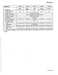 |
Full Advance Engine 24 14 Hg 24 a 1 Retard 311 1110319 1110329 1110330 P 110 HP 180 HP 140 HP lide All Turbo Charged |
 |
 |
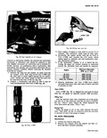
test lamp of not more than 12 volts or an ohmmeter CAUTION Do not use a 110 volt test lamp to test iodes Test Lamp Method Diode in Heat Sink With the stator previously disconnected |
 |
 |
should be replaced Engine Minimum Allowable RPM 1 4 Hs0 95 H P 2600 R P M 110 H P 2600 R P M 140 H P 1900 R P M Dual Air Cleaner |
 |
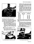 |
110 4 064 t 004 111 126 5 080 f 005 127 142 6 096 t 006 143 155 7 112 f 007 If initial indicator reading is below 025 replace thrust washer |
 |
 |
hose from the upper engine shroud The cooler or tempering air will maintain a temperature of about 110 F during normal vehicle operation while the heated air entering the inlet case may reach |
 |
 |
required 7 If necessary remove the valve body screw assembly and clean Also check that the 110 ring seal us d between the pick up and the valve body is in g condition L NEEDLE |
 |
 |
regardless of the ambient temperature or humidity Grille Air Temperature 70 800 90 1000 110 1200 Engine rpm 2000 Compressor 150 165 205 220 265 295Head Pressure 160 175 215 230 275 305 Compressor Suction |
 |
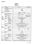 |
Material Housing Attachment to Engine 9 Bolt I 3 8I CH N 7 TurboaAir 164 Turbocharged 164 110 150 164 3 Speed 4 Speed Sihgle Dry Disc Centrifugal 1250 1450 1275 1475 Steel Straps Cast |


