| Book |
Page |
Context |
 |
 |
Assemblies 6 45 Disassembly 6 45 Cleaning and Inspection 6 45 Cylinder 6 45 Piston 6 46 Piston Pin 6 46 Connecting Rod 6 46 Assembly 6 46 Piston and Connecting Rods 6 46 Piston |
|
 |
Repair of Transmission Components 7 39 Front Pump 7 40 Clutch Drum 7 41 Turbine Shaft 7 46 Pump Shaft 46 Rear Pump and Reverse Piston Assembly 7 46 Converter 7 48 Planet Carrier Assembly |
|
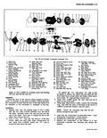 |
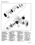
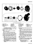
46 45 44 43 42 38 37 Fig 39 Six Cylinder C 1 Shaft Nut 14 Shaft Seal Seat 2 Clutch Hub Retainer Ring Retainer Ring 15 Shaft Seal Seat 3 Spacer 16 Shaft Seal ...
Valve Plate 33 Piston Rear Boll Sect 45 Oil Pump Drive Gear 34 Piston Rear Drive Boll 46 Oil Pump Driven Gear 35 Piston Ring 47 Rear Head to Shell 36 Drive Shaft and Wobble |
|
 |
46 50 45 44 3 3w 38 34 I 3 Fig 7A 13 Manual rarun 1 Input Shaft 16 Clutch Gear 2 2 Mairlshaft Bearing 17 Snap Ring 31 3 Moinshaft Bearing Retaining 18 Clutch ...
B611 44 Reverse Idler Gear Shaft Lock Detent Spring Pin I Roll Pin 45 Countergear Shaft Interlock 46 Countergear Front Needle t Roll Pin Thrust Bearing Washer L First and Reverse Shift Fork 47 Countergear |
|
 |
46 45 44 43 42 41 40 Fig 7B 1 Corvpir Four Speed T nsm l Clutch Gear Bearing Cover 15 lst Blacker Ring 2 Clutch Gear 16 Reverse Shifter Lever 3 Countershaft 17 Reverse ...
Fork Shaft 44 Shifter Shaft Seal 31 Interlock 45 Shifter Shaft 32 3 4 Shift Fork Shaft 46 1 2 Shift Fork Shaft 33 3 4 Shift Fork Shaft Detent Detent Ball and Ball ankl |
|
 |
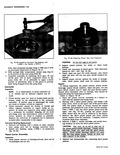
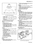
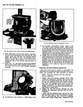
differential carrier F n k 4 Fig 45 Rear Strut Rod Lowered f I 7 r Fig 46 Rear Axle Disconnected 11 Disconnect left and right rear strut rod brackets from differential carrier ...
then swing rods down 12 Disconnect inner universal joints fig 46 13 On automatic transmission equipped vehicles disconnect transmission shift cable NOTE Disconnect transmission shift cable by removing bolt retaining cable at transmission case then |
|
 |
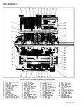
01bl 50 48 52 49 46 57 ss 59 rglide Exploded View 30 Transmission Throttle Valve 44 Of I Pan Gasket Leveir and Shaft Assembly 45 Oi I Pan 31 Monlwl Valve Lever 46 |
|
 |
carrier housing J 9560 1 into the short planet pinion from the Upper end fig 7E 46 pushing the planet pinion shaft ahead until the tool is centered in the pinion 3 Remove the short |
|
 |
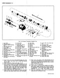
Ring 29 Converter Pump 44 Ring Gear 30 Starter Gear 45 Valve Body Transfer Plate 31 Stator 46 Valve Body 32 Turbine 47 Oil Pick up Pipe 33 Engine Flex Plate 48 Low Servo Piston |
|
 |
washers and if necessary replace all that are worn or damaged t J s t 4 Rpm 46 |
|
 |
then install retaining snap ring b Position a dial indicator with point resting on the bearing fig 46 and set indicator needle at zero c Push the bearing upward against the retaining ring and then |
|
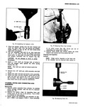 |
Place assembly 1 I r X ed t F w v s m m n INSTALLER 46 ADAPTER SUPPORT |
|
 |
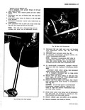
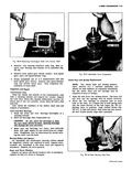
crankcase 4 46 4 49 Fig 29 Blower Bearing Re0acement torque bolts to specifications tube blower 5 Install blower and blower pulley and torque to specifications using a new 11011 ring Install upper shroud |
|
 |
differential assembly with one hand until there is zero backlash between the ring gear and pinion fig 46 Mark this point with a crayon or pencil then back off adjusting sleeve three to four full |
|
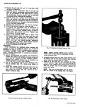 |
discharge crossover tube using a fiber block and mallet fig 48 Discard the discharge crossover tube Fig 46 Removing Suction Crossover Cover Fig 47 Unseating Diachorge Crossover Tube NOTE Before driving cylinder apart position wobble |