| Book |
Page |
Context |
 |
 |
CHASSIS I CORVAIR 500 7C IN Page Lighting System 8 46 Headlamps 8 46 Replacement 8 46 Adjustment 8 46 T 3 Aimers 8 48 Aiming Screen Method 8 52 Lighting Switch Replacement |
 |
 |
Corvairs is a single unit which includes the exhaust pipes muffler and tail pipe fig 9 46 The exhaust pipes are packing flange connected to the exhaust manifolds Both pipes turn towards the right side ...
shell providing extra long life Removal and Installation 1 Remove the four mounting nuts A Figure 9 46 2 Remove bolt B Figure 9 46 PERATIONS FUEL TANK Removal and installation 1 Drain gas tank ...
muffler and exhaust pipe assembly from under car r AF 9 s v sq r Fig 9 46 Exhaust SysNm and Mounting |
 |
 |
Back Window Assembly 10 43 Engine Compartment 10 45 Lid 10 45 Lid Hinge 10 46 Lid Support 10 46 Lid Latch 10 46 Lower Gutter Sealing Strip 10 47 Exterior Mouldings 700 Models |
 |
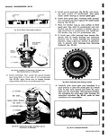 |
diameter using a generous amount of petroleum jelly to prevent roller bearings from becoming displaced fig 613 46 1 v Fig 6D 46 Clutch Gear Roller Bearings Installed 9 Carefully slide clutch gear onto mainshaft |
 |
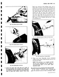 |
Piercing Cement Cartridge Fig 3 45 Inurting Cement in Puncture Fig 3 46 Starting Plug into Puncture 3 Insert the metal tube with plug into nozzle o the plug insertion tool turning to the right ...
entire metal tube into the puncture hole up to the base of the nozzle fig 3 46 Now press red spring stopper and squeeze the balance of cement into the tire fig 3 47 Retract |
 |
 |
housing 4 Pull the side cover with the sector and shaft from the housing fig 4 46 i r p arrst L y Fig 4 46 Removing Cover and Sector Shaft NOTE If the sector |
 |
 |
Ground Place one lead on the connector bar and the other on the field frame fig 8 46 If the lamp lights the field coils are grounded Repairs Loose Electrical Connections When an open soldered ...
commutator lightly with No 00 sandpaper to remove any slight burrs left from undercutting Fig B 46 Field Coil Test for Ground |
 |
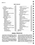 |
Journal Inspection 6A 43 Main Bearing Clearance 6A 43 Connecting Rod Bearings 6A 45 Valve Lifters 6A 46 Flywheel Housing Seal 6A 46 Engine Assembly Engine Removed 6A 47 Crankshaft 6A 47 Camshaft |
 |
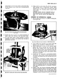 |
support ASSEMBLY OF DIFFERENTIAL CARRIER 1 Mount differential carrier in J 3289 O1 holding fixture fig 6C 46 ...
46 Differential Carrier Installed in J 3289 Holding Fixture 2 Insert differential assembly into carrier with side bearing cones installed on differential hubs 3 While differential is loose in the carrier insert pinion into carrier |
 |
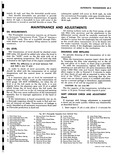 |
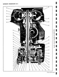
Ring 29 Converter Pump 44 Ring Gear 30 Starter Gear 45 Valve Body Ditch Plate 31 Stator 46 Valve Body 47 Oil Pick up Pipe 32 Turbine 48 Low Servo Piston 33 Engine flex Plate |
 |
 |
Total effective area 197 9 sq in Distribution of Braking Effort theoretical On front wheels 46 On rear wheels 54 Brake Linings Material Full molded asbestos composition Width front and rear 1 75 Thickness |
 |
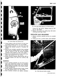 |
ventilator 1 z i r I l i l 1 h i T r s s 11 46 |
 |
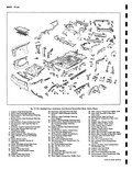 |
Bumper Center Zianger Opening 44 Support Engine Mount Lower 45 Plate Engine Mount Tapped i Panel Reinforcement 46 Panel Rear End Inner 47 Support Engine Mount Upper ngine Compartment 48 Panel Rear End Outer tinge |
 |
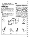 |
Check weatherstrip clips for proper contour and reform if necessary using Tool J 5984 fig 10 46 3 Check all attaching hole sealing plugs If sealing plugs are loose and will not remain engaged |
 |
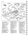 |
Cover 44 Plate Engine Mount Tapped ngine Compartment Side 45 Reinforcement Rear End Panel Left anger Opening 46 Filler Rear End Inner Panel At Bumper Depression Left i Panel Reinforcement 47 Panel Rear End Inner |
 |
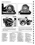 |
Transmission Throttle Valve 44 Oil Pon Gasket Lever Shaft Seal 45 Oil Pon 30 Transmission Throttle Valve 46 Oil Pan Attaching Screws Lever and Shaft 47 Oil Pick up Pipe Attaching 31 Manual Valve Lever |
 |
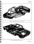 |
46 z l i on structi on Lower Front |
 |
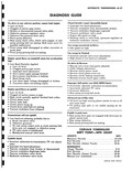 |
Throttle 8 12 Full Throttle 38 44 Part Throttle Detent Touch 23 30 Manual Low Inhibited 41 46 CaRVA1R SWOP MANUAL |
 |
 |
Series 8 1 Engine Electrical 8 1 Wiring Diagrams 8 39 Chassis Electrical 8 46 ENGINE CORVAIR 500 71 II Page General Trouble Shooting 8 2 Battery 8 2 Generator 8 3 Regulator |
 |
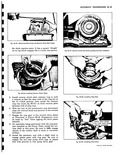 |
which engages the 4 o clock case groove s t I c Fig 6E 46 Installing Reverse Clutch Plates 5 Install reverse clutch plate retainer ring in sucl a manner so that the open ends |
 |
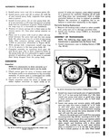 |
securing to 9 11 ft lbs 4 Install the reverse clutch drive and reaction plates fig 6E 46 alternately starting with a reaction plate steel and finishing with a drive plate faced The notched |
 |
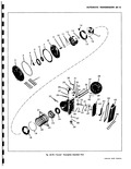 |
46 57 47 58 o o P 59 Pow rglide Exploded View CORVAIR SHOP MANUAL |
 |
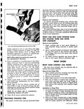 |
WEATHERSTRIP CLIP REFORMER r TOOL J 5984 I CLIP o Fig 10 46 Reforming Weatherstrip Clips with Tool J 5984 sembly channel to one 1 inch below lock pillar section of frame as shown |
 |
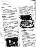 |
piston shaft with a screwdriv icle tab iisthe i a the ew ert 46 IMPROVISED STRAP ton Fig 611 10 Rtmoving Volvo body on CAUTION Do not remove piston in vehicle unless low band screw |
 |
 |
46 |
 |
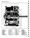 |
Shifter Shaft Seal 33 3 4 Shift Fork Shaft Defenf Ball 45 Shifter Shaft and Spring 46 1 2 Shift Fork Shaft Detent 34 Drain Plug Roll and Spring 35 3 4 Detenf and Interlock |
 |
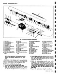 |
Gear Shaft lock 30 Detent Spring Fin 31 Roll Pin 43 Counter Gear Shot t 32 Interlock 46 Counter Gear Front Bearings 33 Roll Pin spacer 34 first end Reverse Shift Fork 47 Counter Gear |
 |
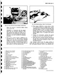 |
Pinion Front Seal Auto Trans only a Lock Tab 45 Pinion Adjusting Sleeve Seal Ring embly 46 Pinion Shaft Bushing Auto Trans only 47 Differential Components Ice A Ring Gear Bolts and Lock Washers diusfing |
 |
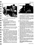 |
rear engine mount 45 Install blower and blower pulley to crankcase cover blower bearing hub assembly 46 Install front shrouds figures 6A 15 and 16 Install left and right side shields |
 |
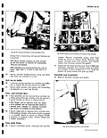 |
Cylinder Piston and Rod washer Remove crankshaft pulley with Tool J 8105 as shown in Figure 6A 46 Remove rear engine housing bolts and washers and remove engine rear housing Discard the gasket 41 Disconnect |
 |
 |
46 |


